terça-feira, 29 de abril de 2014
segunda-feira, 28 de abril de 2014
Marsden Tromba Vector Calculus
Internet Supplement for Vector Calculus
*
*
1 The Geometry of Euclidean Space ........................ 31
2 Differentiation,,,,,,,,,,,,,,,,,,,,,,,,.,,,,,............... 124
3 Higher-Order Derivatives; Maxima and Minima........ 211
4 Vector-Valued Functions ................................. 291
5 Double and Triple Integrals ............................... 347
6 The Change of Variables .................................. 398
7 Integrals Over Paths and surfaces ....................... 451
8 The Integral Theorems of Vector Analysis ............. 548
M217 - Análise Infinitesimal - 2013/2014 - 1S
Aula nº. 1 - 17/09/2013
Aula nº. 2 - 19/09/2013
Introdução ao estudo das equações diferenciais. Definições básicas. Equações ordinárias e equações de derivadas parciais. Soluções gerais e particulares de uma equação. Famílias de curvas associadas, exemplos. Equações de 1ªordem : equações de variáveis separadas. Equações diferenciais exactas. Métodos de resolução.
Aula nº. 3 - 24/09/2013
Equações exactas, exercícios. Funções homogéneas. Equações homogéneas e equações redutíveis a homogéneas. Outras equações redutíveies a equações de variáveis separadas.
Aula nº. 4 - 26/09/2013
Equações Lineares de 1ª ordem. Factores Integrantes Equações de Bernoulli. Equações de Ricatti.
Aula nº. 5 - 01/10/2013
Equações de Ricatti(continuação). Trajectórias ortogonais. Exemplos. Equações diferenciais de ordem superior. Alguns casos "fáceis" de resolver Exemplos.
Aula nº. 6 - 03/10/2013
Equações diferenciais de ordem superior. Alguns casos "fáceis" de resolver (continuação) Equações diferenciais Lineares. Notações básicas. Enunciado do teorema de existência e unicidade de soluções. A matriz de Wronski. O Wronskiano de uma família de funcões. Funções linearmente independentes. Critério de independência linear.Exemplos de funções linearmente independentes. Equações diferenciais lineares homogéneas Equações não homogéneas. Solução geral. Exemplos.
Aula nº. 7 - 08/10/2013
Espaço vectorial das soluções da equação homogénea. Soluções fundamentais( base do espaço)
Aula nº. 8 - 10/10/2013
Equações diferenciais lineares homogéneas de coeficientes constantes. Resolução de exercícios
Aula nº. 9 - 15/10/2013
O Wronskiano de um sistema fundamental de soluções. Diferenciabilidade da solução da equação homogénea. Referência ao Anel dos operadores lineares de coeficientes constantes. Algumas propriedades sobre o anel dos polinómios em IR. Relação com o anel dos operadores diferenciais. Polinómio característico de um operador linear de coeficientes constantes (Decomposição do operador em factores irredutíveis) Soluções de L(y) = 0 . Base de Ker L.
Aula nº. 10 - 17/10/2013
Soluções de L(y) = 0 . Base de Ker L. Estudo da equação (D – aI)^n(y) = 0 Estudo da equação {(D – aI)^2 +b^2I]^m (y) ) = 0. Resolução de exercícios.
Aula nº. 11 - 22/10/2013
Raízes racionais de polinómios de coeficientes inteiros. Método da variação das constantes para o cálculo de uma solução particular e sua justificação usando teoria de operadores lineares. Resolução de exercícios.
Aula nº. 12 - 24/10/2013
Determinação das soluções particulares. Método do polinómio aniquilador.( continuação) /variação das constantes.
Aula nº. 13 - 29/10/2013
Determinação das soluções particulares: Método da variação dos parâmetros ou método de Wronski Resolução de exercícios. Equações lineares de coeficientes não constantes. Resolução de equações diferenciais lineares por mudanças de parâmetro.Equações de Euler.
Aula nº. 14 - 31/10/2013
Pontos ordinários e pontos singulares de equações diferenciais lineares. Resolução de equações diferencias por séries de Potências. Exemplos.
Aula nº. 15 - 05/11/2013
Resolução de exercícios sobre equações diferenciais usando séries de potências na vizinhaça de pontos ordinários. Equação de Bessel . Referência ao método de Frobenius ( solução em série na vizinhaçan de pontos singulares). Transformadas de Lapace. Definição, propriedades. Transformadas de Laplace de algumas funções. Transformada inversa de Laplace.
Aula nº. 16 - 07/11/2013
Condições para que exista transformada de Laplace. Exercícios de aplicação. Mais propriedades da Transformada Tansformada da derivada. Transformada de função periódicas. Aplicação à resolução de equações diferenciais lineares de coeficientes constantes. Exemplos
Aula nº. 17 - 12/11/2013
Transformada de Laplace de funções periódicas. Mais propriedades das transformadas de Laplace. Traansformada do Integral Função de Heaviside. Transformadas de Laplace da funçâo de Heaviside. 2º Teorema de translacção. Resolução de exercícios
Aula nº. 18 - 14/11/2013
Resolução de exercícios com a transformada de Laplace da Função de Heaviside. "Função Delta Dirac"
Aula nº. 19 - 19/11/2013
Justificação Física do método de Delta de Dirac. Exemplos. Integral de Convolução.Propriedades.
Aula nº. 20 - 21/11/2013
Integral de Convolução.Propriedades. Teorema de Convolução. Aplicações. Sistemas de Equações diferenciais.
Aula nº. 21 - 26/11/2013
Exercícios sobre sistemas de equações diferenciais. Integrais de linha de campos escalares. Exercícios e aplicações.
Aula nº. 22 - 28/11/2013
Integrais de linha de campos vectoriais. Aplicações e exemplos.
Aula nº. 23 - 03/12/2013
Propriedades dos integrais de linha. Integrais de linha independentes do caminho. Campos de gradientes. Abertos conexos por arcos. Teste para independência de caminho
Aula nº. 24 - 05/12/2013
Teste para independência de caminho em domínios simplesmente conexos ( demonstração do caso de domínios convexos). Teorema de Green. Aplicações. Cálculo da área de um domínio
Aula nº. 25 - 10/12/2013
Demonstração do Teorema de Green. Teorema de Green em Domínios multiconexos. Exemplos de aplicação. Casos particulares do teorema de Green.
Aula nº. 26 - 12/12/2013
Superfícies parametrizadas num espaço euclidiano. Exemplos. Exemplos de superfícies parametrizadas . Algumas considerações sobre superfícies no caso geral. Exemplos. Cálculo dos coeficientes da primeira forma fundamental. Área de uma superfície parametrizada e integral de superfície de uma funcão escalar.Interpretação geométrica. Exemplos. Parametrização de uma superfície dada pelo gráfico de uma função Cálculo da respectiva área. Exemplos.
Aula nº. 27 - 17/12/2013
Aula de dúvidas
Aula nº. 28 - 19/12/2013
Parametrização de uma superfície de revolução. Cálculo da respectivas área. Exemplos. Integral de superfície de uma função vectorial. Exemplos. Teorema da Divergência de Gauss. Teorema de Stokes. Exercícios.( Lei de Gauss)
Marsden Jerrold E.; Vector calculus. ISBN: 7167-4992-0
Bronson Richard; Moderna introdução às equações diferenciais
Swokowski Earl W.; Calculo com geometria analitica. vol. i. 2ª ed. trad. ISBN: 85-346-0308-1
Young Eutiquio C.; Vector and tensor analysis. ISBN: 0-8247-6671-7
Boyce William E.; Elementary differential equations and boundary value problems. ISBN: 0-471-31999-6
Marsden Jerrold; Calculus iii. 2nd ed. ISBN: 0-387-90985-0
Bibliografia Obrigatória
Madureira Luísa; Problemas de equações diferenciais ordinárias e transformadas de Laplace. ISBN: 978-972-752-124-1Marsden Jerrold E.; Vector calculus. ISBN: 7167-4992-0
Bibliografia Complementar
Braun M.; Differential equations and their applications. ISBN: 0-387-90114-0Bronson Richard; Moderna introdução às equações diferenciais
Swokowski Earl W.; Calculo com geometria analitica. vol. i. 2ª ed. trad. ISBN: 85-346-0308-1
Young Eutiquio C.; Vector and tensor analysis. ISBN: 0-8247-6671-7
Boyce William E.; Elementary differential equations and boundary value problems. ISBN: 0-471-31999-6
Marsden Jerrold; Calculus iii. 2nd ed. ISBN: 0-387-90985-0
sexta-feira, 25 de abril de 2014
As Regras de Ouro dos Amp-Op
The Op-amp Golden Rules
From Horowitz & Hill:
For an op-amp with external feedback
I. The output attempts to do whatever is necessary to make the voltage difference between the inputs zero. |
| |
II. The inputs draw no current. |
|
Comments on 1: The voltage gain of a real op-amp is so high that a fraction of a millivolt input will swing the output over its full range. Practically, that amounts to rule 1.
Comments on 2: The input current is so low (0.08 microamps for the 741, picoamps for an FET-input op-amp) that rule 2 is practically correct.
| The ideal op-amp |
O Amp-Op Ideal
The Ideal Op-amp
The IC Op-amp comes so close to ideal performance that it is useful to state the characteristics of an ideal amplifier without regard to what is inside the package.
|
|
These characteristics lead to the golden rules for op-amps. They allow you to logically deduce the operation of any op-amp circuit.
O Amp-Op 741
The 741 Op-amp
The most common and most famous op-amp is the mA741C or just 741, which is packaged in an 8-pin mini-DIP. The integrated circuit contains 20 transistors and 11 resistors. Introduced by Fairchild in 1968, the 741 and subsequent IC op-amps including FET-input op-amps have become the standard tool for achievingamplification and a host of other tasks. Though it has some practical limitations, the 741 is an electronic bargain at less than a dollar.
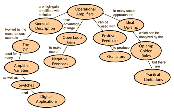
Amplificadores Operacionais
Operational Amplifiers
The term operational amplifier or "op-amp" refers to a class of high-gain DC coupled amplifiers with two inputs and a single output. The modern integrated circuit version is typified by the famous 741 op-amp. Some of the general characteristics of the IC version are:
| 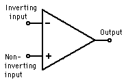 |
Their characteristics often approach that of the ideal op-amp and can be understood with the help of the golden rules.
quinta-feira, 24 de abril de 2014
Leis de Conservação
Conservation Laws
If a system does not interact with its environment in any way, then certain mechanical properties of the system cannot change. They are sometimes called "constants of the motion". These quantities are said to be "conserved" and the conservation laws which result can be considered to be the most fundamental principles of mechanics. In mechanics, examples of conserved quantities are energy, momentum, and angular momentum. The conservation laws are exact for an isolated system.

Stated here as principles of mechanics, these conservation laws have far-reaching implications as symmetries of nature which we do not see violated. They serve as a strong constraint on any theory in any branch of science.
descarga de um Condensador
Capacitor Discharge
An application of homogeneous differential equations
A first order homogeneous differential equation
 .
.
For the process of discharging a capacitor C, which is initially charged to the voltage of a battery Vb, the equation is

Using the boundary condition and identifying the terms corresponding to the general solution, the solutions for the charge on the capacitor and the current are:
 .
.
Since the voltage on the capacitor during the discharge is strictly determined by the charge on the capacitor, it follows the same pattern.
 .
.Relações Básicas Circuitos CC
Basic DC Circuit Relationships
| DC circuits can be completely analyzed with these four relationships. | ||
| The net voltage change is equal to zero around any closed loop. (This is an application of the principle of conservation of energy.) | ||
| The electric current in = electric current out of any junction. (Conservation of charge) |
| Water analogy to DC circuits |
Exemplos Circuitos CC
DC Circuit Examples
The basic tools for solving D C circuit problems are Ohm's Law, the power relationship, the voltage law, and the current law. The following configurations are typical; details may be examined by clicking on the diagram for the desired circuit.
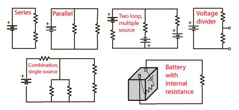
Divisor de Voltagem
Voltage Divider
The two resistor voltage divider is used often to supply a voltage different from that of an available battery or power supply. In application the output voltage depends upon the resistance of the load it drives.
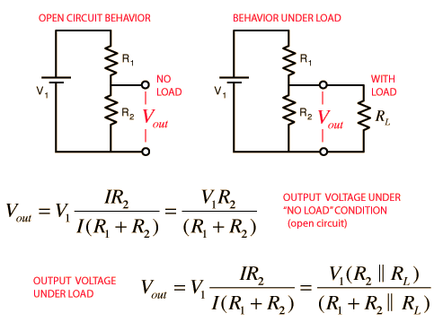
The voltage divider is a very important basic circuit, and exploring the calculation above with various values can give you insight into a large number of practical circuit applications. One practical consideration is that a larger value of R2compared to R1 will give you a larger output voltage. But if your load resistance RLis smaller than R2, you will diminish the output voltage and require a larger current and total power from the power supply. You would find upon exploration that for a given set of values for the voltage divider (R1 and R2), you will get more power to the load if you decrease the load resistor RL but is comes at the expense of higher current and power from the power supply.
Note: To avoid dealing with so many short circuits, divider resistors with value zero will default to 1 when the voltage is changed and the load will default to 1000. They can be changed back to a zero value if you wish to explore the effects of short circuits. Ohms are indicated as the resistance unit, but kilohms are more common and of course the calculation is the same.
| DC circuit examples | AC voltage divider |
Relações Triângulo Rectângulo
Right Triangle Relationships
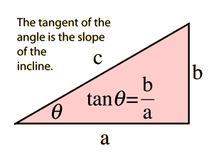 | The hypotenuse of a right triangle is related to the sides by the Pythagorean relationship:  |
Given any two sides, the angles may be found using the triangle trigonometric relationships. If the hypotenuse and one side are known, the other side may be calculated from:

Funções Trigonometricas Básicas
Basic Trigonometric Functions
The basic trigonometric functions can be defined in terms of a right triangle. For the angle θ at one apex of the right triangle the functions can be defined by:
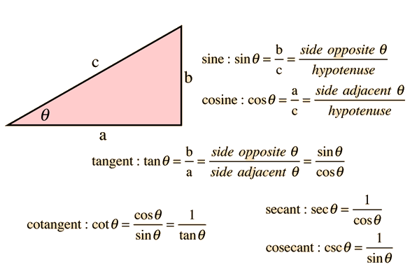
Basic triangle geometry
Aplicação de Complexos Conjugados
Applications of Complex Conjugates
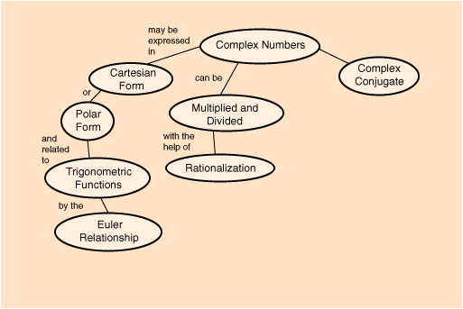
When a real positive definite quantity is needed from a real function, the square of the function can be used. In the case of a complex function, the complex conjugateis used to accomplish that purpose. The product of a complex number and its complex conjugate is the complex number analog to squaring a real function. The complex conjugate is used in the rationalization of complex numbers and for finding the amplitude of the polar form of a complex number.
One application of the complex conjugate in physics is in finding the probability in quantum mechanics. Since the wavefunction which defines the probability amplitude may be a complex function, the probability is defined in terms of the complex conjugate to obtain a real value.

Complexo Conjugado
Complex Conjugate
The conjugate of a complex number is that number with the sign of the imaginary part reversed

The utility of the conjugate is that any complex number multiplied by its complex conjugate is a real number:

This operation has practical utility for the rationalization of complex numbers and the square root of the number times its conjugate is the magnitude of the complex number when expressed in polar form.
Applications
Racionalização de Numeros Complexos
Rationalization of Complex Numbers
The division of complex numbers which are expressed in cartesian form is facilitated by a process called rationalization. The formation of a fraction

presents difficulties because of the imaginary part of the denominator. The denominator can be forced to be real by multiplying both numerator and denominator by the conjugate of the denominator.

Expanding puts the result of the division in cartesian form again.

Calculation for multiplication and division
Norton Current
Norton Current
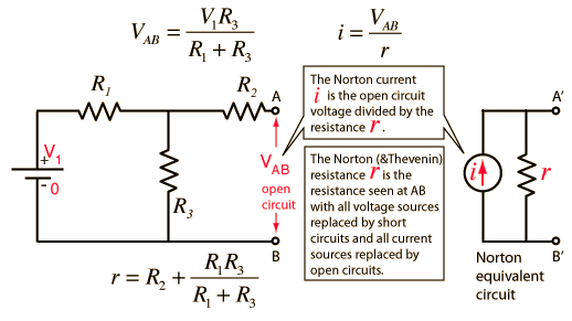
The value i for the current used in Norton's Theorem is found by determining the open circuit voltage at the terminals AB and dividing it by the Norton resistance r.
| Norton resistance | Numerical example | Thevenin equivalent |
Thevenin/Norton Resistance
Thevenin/Norton Resistance
The Thevenin resistance r used in Thevenin's Theorem is the resistance measured at terminals AB with all voltage sources replaced by short circuits and all current sources replaced by open circuits. It can also be calculated by dividing the open circuit voltage by the short circuit current at AB, but the previous method is usually preferable and gives
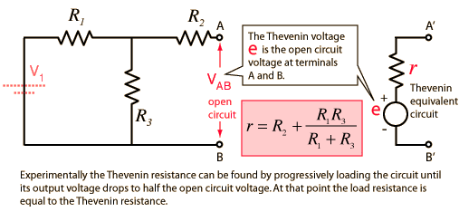
| Thevenin voltage | Numerical example | Norton equivalent |
Tensão de Thevenin
Thevenin Voltage
The Thevenin voltage e used in Thevenin's Theorem is an ideal voltage source equal to the open circuit voltage at the terminals. In the example below, the resistance R2does not affect this voltage and the resistances R1 and R3 form a voltage divider, giving
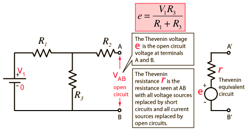
| Thevenin resistance | Numerical example | Norton equivalent |
Thevenin's Theorem
Thevenin's Theorem
Any combination of batteries and resistances with two terminals can be replaced by a single voltage source e and a single series resistor r. The value of e is the open circuit voltage at the terminals, and the value of r is e divided by the current with the terminals short circuited.
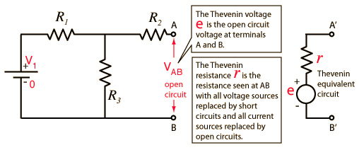
| Thevenin voltage | Thevenin resistance | Numerical example | Norton equivalent |
| to AC Version | Application in Digital to Analog Converter |
Teorema de Norton
Norton's Theorem
Any collection of batteries and resistances with two terminals is electrically equivalent to an ideal current source i in parallel with a single resistor r. The value of r is the same as that in the Thevenin equivalent and the current i can be found by dividing the open circuit voltage by r.
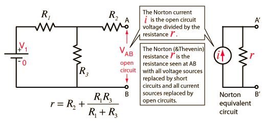
| Norton current | Norton resistance | Numerical example | Thevenin equivalent |
Fontes de Corrente e Tensão
Voltage and Current Sources
Real voltage sources can be represented as ideal voltage sources in series with a resistance r, the ideal voltage source having zero resistance. Real current sources can be represented as ideal current sources in parallel with a resistance r, the ideal current source having infinite resistance.
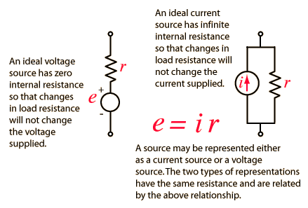
Such ideal voltage and current sources are used in modeling real circuits withThevenin's theorem and Norton's theorem.
Teorema de Thevenin CA
AC Thevenin's Theorem
Any combination of sinusoidal AC sources and impedances with two terminals can be replaced by a single voltage source e and a single series impedance z. The value of e is the open circuit voltage at the terminals, and the value of z is e divided by the current with the terminals short circuited. In this case, that impedance evaluation involves a series-parallel combination.
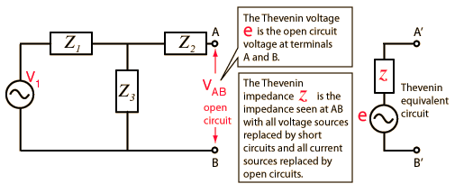
| Thevenin voltage | Thevenin resistance | Numerical example | Norton equivalent |
| to DC Version |
Combinação Série - Paralelo
Series-Parallel Combination
Most networks in AC circuits can be broken into blocks no more complicated than the one below. The complex impedance approach provides the tool necessary to reduce such a combination to an equivalent impedance. This kind of combination may be encountered in the development of an AC Thevenin equivalent for the analysis of an AC circuit.
 |
|
| The parallel part of the impedance can be put in the form |  |
| which can be rationalized by the operation : |  , , |
Circuito RLC Paralelo
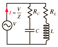
RLC Parallel Circuit
Finding the impedance of a parallel RLC circuit is considerably more difficult than finding the series RLC impedance. This is because each branch has a phase angle and they cannot be combined in a simple way. The impedance of the parallel branches combine in the same way that parallel resistors combine:
 | 
|
Subscrever:
Mensagens (Atom)


